#Install Updates
sudo apt-get update
sudo apt-get upgrade

#see USB devices
lsusb

#Install GPS software
sudo apt -y install gpsd gpsd-clients python-gps

#Edit GPS config file
sudo nano /etc/default/gpsd

#Add this to file
START_DAEMON=”true”

USBAUTO=”true”

DEVICES=”/dev/ttyACM0″

GPSD_OPTIONS=”-n”

#Install chrony
sudo apt-get install chrony

#reboot pi

#check to see if services are running
systemctl is-active gpsd
systemctl is-active chronyd

#Check GPS output
cgps – s
gpsmon -n

#Edit chrony config file
sudo nano /etc/chrony/chrony.conf

#Add this to end of file
refclock SHM 0 offset 0.5 delay 0.2 refid NMEA

#Check Chrony Output
sudo chronyc sources -v

# Check chrony output
sudo chronyc tracking

#Force time sync
sudo chronyc makestep
Category: PROGRAMMING
HOW TO CLEAR AZURE IOTEDGE LOGS FILE
Azure IoTEdge consist of two default in house agents and one or more custom modules. Those two default agents are edgeAgent and hubAgent. The custom module it self is upto the developer who builds it. Those agents and custom module must have log files some where. By default their logs files are on /var/lib/docker/containers folders. But to get access that folder you need to be SUPERUSER.
- On the prompt type : sudo su
- Then type cd /var/lib/docker/containers
- Then type ls -l to show all the contents inside that folder.
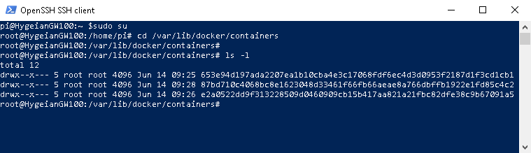
You would see folders that their names are in long random unique characters. Two of those are logging folder for our edgeAgent and hubAgent. The third one belongs to our custom module (in my scenario i only have 1 custom module).
Now, we need to go inside each folders one by one and remove the logs files.
- Type cd 653e94d197ada2207ea1b10cba4e3c17068fdf6ec4d3d0953f2187d1f3cd1cb1, in your case the name of the folder would be another long unique random characters.
- Once you are inside that folder, type ls -l on the prompt to view all the content under that folder.
- You would see many other folders and files, but just focus on the folder that has a name local-logs.

4. Now type cd local-logs followed by ls -l. You would see a file named as container.log.

5. Delete that container.log file type typing rm container.log on the prompt.
6. To take effect, you need to reboot the raspberry pi.
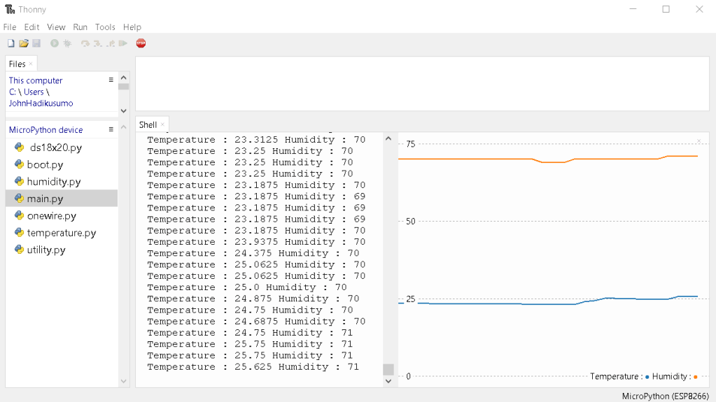
SETTING UP ESP8266 TO SEND TEMPERATURE AND HUMIDITY DATA TO YOUR MQTT BROKER

1). DS18B20 Digital temperature

2) DHT11 Humidity Sensor

3) ESP8266 development board

4) Bread board ( 2 unit attached together)

The reason why i am using 2 bread board attached together because the width of my ESP8266 simply doesn’t fit to be placed normally in the middle of the bread board. So bascially i have to attach 2 bread board and place my ESP8266 in the middle of the joining part.
5) Cable connectors (8 pieces)
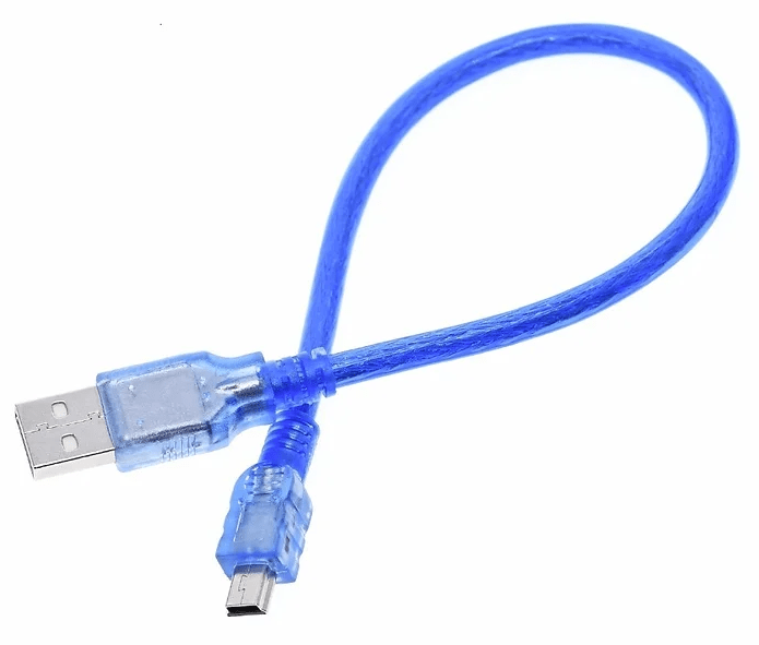
6) USB 2 to USB Mini cable
from machine import Pin
import machine
import time
import dht


class Humidity:
    def __init__(self, pin):
        self.pin = machine.Pin(pin)
        self.sensor = dht.DHT11(self.pin)

    def read(self):
        self.sensor.measure()
	return self.sensor.humidity()
temperature.py
from machine import Pin
import machine
import utime
import onewire, ds18x20, time


class Temperature:
    def __init__(self, pin):
        self.loop = 1
        self.pin = machine.Pin(pin)
        self.sensor = ds18x20.DS18X20(onewire.OneWire(self.pin))
        self.roms = self.sensor.scan()

    def read(self):
        self.sensor.convert_temp()
        time.sleep_ms(250)
        return self.sensor.read_temp(self.roms[0])
ds18x20.py
# DS18x20 temperature sensor driver for MicroPython.
# MIT license; Copyright (c) 2016 Damien P. George

from micropython import const

_CONVERT = const(0x44)
_RD_SCRATCH = const(0xBE)
_WR_SCRATCH = const(0x4E)


class DS18X20:
    def __init__(self, onewire):
        self.ow = onewire
        self.buf = bytearray(9)

    def scan(self):
        return [rom for rom in self.ow.scan() if rom[0] in (0x10, 0x22, 0x28)]

    def convert_temp(self):
        self.ow.reset(True)
        self.ow.writebyte(self.ow.SKIP_ROM)
        self.ow.writebyte(_CONVERT)

    def read_scratch(self, rom):
        self.ow.reset(True)
        self.ow.select_rom(rom)
        self.ow.writebyte(_RD_SCRATCH)
        self.ow.readinto(self.buf)
        if self.ow.crc8(self.buf):
            raise Exception("CRC error")
        return self.buf

    def write_scratch(self, rom, buf):
        self.ow.reset(True)
        self.ow.select_rom(rom)
        self.ow.writebyte(_WR_SCRATCH)
        self.ow.write(buf)

    def read_temp(self, rom):
        buf = self.read_scratch(rom)
        if rom[0] == 0x10:
            if buf[1]:
                t = buf[0] >> 1 | 0x80
                t = -((~t + 1) & 0xFF)
            else:
                t = buf[0] >> 1
            return t - 0.25 + (buf[7] - buf[6]) / buf[7]
        else:
            t = buf[1] << 8 | buf[0]
            if t & 0x8000:  # sign bit set
                t = -((t ^ 0xFFFF) + 1)
            return t / 16
onewire.py
# 1-Wire driver for MicroPython
# MIT license; Copyright (c) 2016 Damien P. George

import _onewire as _ow


class OneWireError(Exception):
    pass


class OneWire:
    SEARCH_ROM = 0xF0
    MATCH_ROM = 0x55
    SKIP_ROM = 0xCC

    def __init__(self, pin):
        self.pin = pin
        self.pin.init(pin.OPEN_DRAIN, pin.PULL_UP)

    def reset(self, required=False):
        reset = _ow.reset(self.pin)
        if required and not reset:
            raise OneWireError
        return reset

    def readbit(self):
        return _ow.readbit(self.pin)

    def readbyte(self):
        return _ow.readbyte(self.pin)

    def readinto(self, buf):
        for i in range(len(buf)):
            buf[i] = _ow.readbyte(self.pin)

    def writebit(self, value):
        return _ow.writebit(self.pin, value)

    def writebyte(self, value):
        return _ow.writebyte(self.pin, value)

    def write(self, buf):
        for b in buf:
            _ow.writebyte(self.pin, b)

    def select_rom(self, rom):
        self.reset()
        self.writebyte(self.MATCH_ROM)
        self.write(rom)

    def scan(self):
        devices = []
        diff = 65
        rom = False
        for i in range(0xFF):
            rom, diff = self._search_rom(rom, diff)
            if rom:
                devices += [rom]
            if diff == 0:
                break
        return devices

    def _search_rom(self, l_rom, diff):
        if not self.reset():
            return None, 0
        self.writebyte(self.SEARCH_ROM)
        if not l_rom:
            l_rom = bytearray(8)
        rom = bytearray(8)
        next_diff = 0
        i = 64
        for byte in range(8):
            r_b = 0
            for bit in range(8):
                b = self.readbit()
                if self.readbit():
                    if b:  # there are no devices or there is an error on the bus
                        return None, 0
                else:
                    if not b:  # collision, two devices with different bit meaning
                        if diff > i or ((l_rom[byte] & (1 << bit)) and diff != i):
                            b = 1
                            next_diff = i
                self.writebit(b)
                if b:
                    r_b |= 1 << bit
                i -= 1
            rom[byte] = r_b
        return rom, next_diff

    def crc8(self, data):
        return _ow.crc8(data)
utility.py
import network
import ubinascii


class Utils:
    @staticmethod
    def macaddress():
        return ubinascii.hexlify(network.WLAN().config('mac'),':').decode()

    @staticmethod
    def connectWIFI(WIFI_SSID,WIFI_PASSWORD):
      wlan = network.WLAN(network.STA_IF)
      wlan.active(True)
      wlan.connect(WIFI_SSID,WIFI_PASSWORD)
      while not wlan.isconnected():
        pass

    @staticmethod
    def doubleDigit(val):
        if(val < 10):
           out = "0" + str(val)
        else:
           out = str(val)
        return out
main.py
import time, temperature, humidity

temperature = temperature.Temperature(14)
humidity = humidity.Humidity(16)

while True:
    print("Temperature : " + str(temperature.read()) + " Humidity : " + str(humidity.read()))
    time.sleep_ms(500)
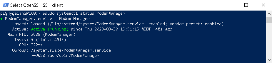
HOW TO ENABLE/DISABLE 4G MODEM ACCESS ON RASPBERRY PI 4 B
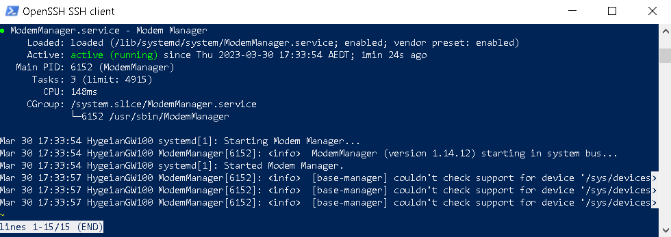
By default Raspberry PI 4 enables the system to access to 4G Modem via Ethernet. There is special service that handles this : ModemManager. Now on the prompt, you can check the status of this 4G modem access by typing : sudo systemctl status ModemManager.
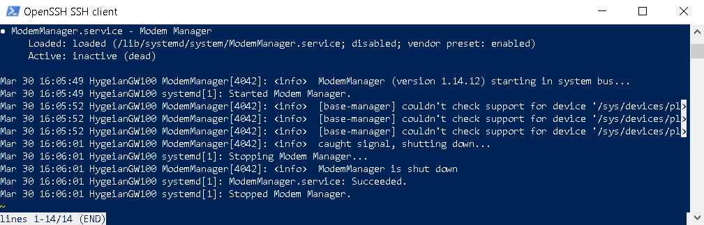
To stop and disable this access you can type : sudo systemctl stop ModemManager on your raspberry pi prompt followed by sudo systemctl disable ModemManager.

Now type sudo systemctl status ModemManager again, and you would see the status is inactive and ModemManager service has been stopped and shut down.
To enable 4G modem access you need to do the opposite what we did above. On the prompt type sudo systemctl enable ModemManager, followed by sudo systemctl start ModemManager.
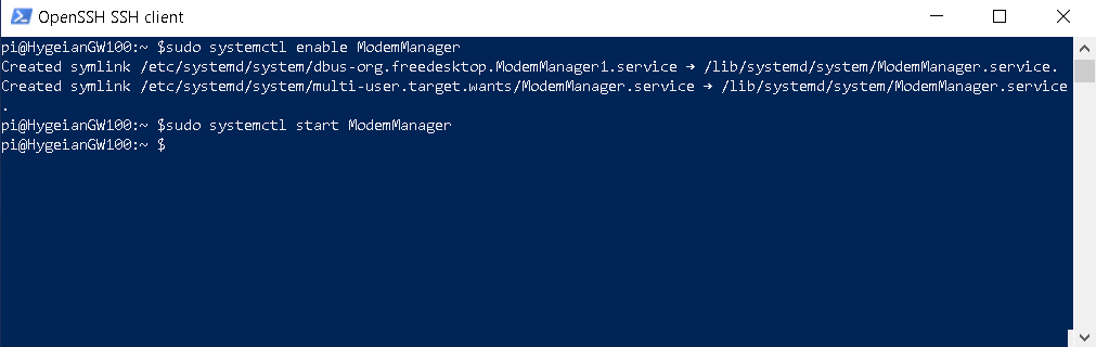
Now type sudo systemctl status ModemManager.
SETTING UP YOUR OWN CERTIFICATE ON AZURE IOTEDGE DEVICE
BLAH BLAH
Create or obtain a root certificate and private key:
openssl genrsa -out root.key 2048
openssl req -new -key root.key -out root.csr
openssl x509 -req -days 365 -in root.csr -signkey root.key -out root.crt
Use the root certificate and private key to generate a certificate authority (CA) certificate and private key:
openssl genrsa -out ca.key 2048
openssl req -new -key ca.key -out ca.csr
openssl x509 -req -days 365 -in ca.csr -CA root.crt -CAkey root.key -CAcreateserial -out ca.crt
Create or obtain a device certificate and private key for your IoT Edge device:
openssl genrsa -out device.key 2048
openssl req -new -key device.key -out device.csr
openssl x509 -req -days 365 -in device.csr -CA ca.crt -CAkey ca.key -CAcreateserial -out device.crt
Use the CA certificate and private key to sign the device certificate and generate a certificate chain:
cat device.crt ca.crt > device-chain.pem
Install the root certificate, CA certificate, and device certificate on your IoT Edge device. You can do this by adding them as trusted certificates to the IoT Edge runtime.
On a Linux-based device, you can copy the certificates to the /etc/ssl/certs directory and run the update-ca-certificates command to update the trusted certificates:
sudo cp root.crt /etc/ssl/certs/
sudo cp ca.crt /etc/ssl/certs/
sudo cp device-chain.pem /etc/ssl/certs/
sudo update-ca-certificates
HOW TO CLEAR ALL CACHE FROM REDIS SERVICE
Open your windows command prompt as administrator, then type redis-cli followed by ENTER.

On redis prompt, type FLUSHALL followed by ENTER
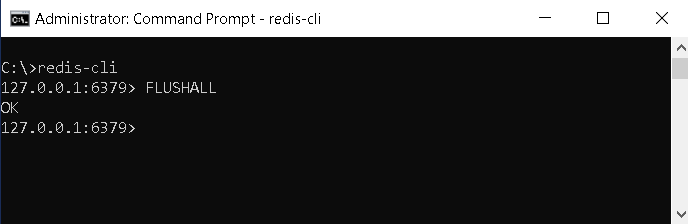
That’s it. Your redis cache has been cleared completely.
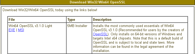
CREATING YOUR OWN PEM FILE using openssl
First thing first, you need to download openssl application installer from the following link : https://slproweb.com/products/Win32OpenSSL.html. Because my computer is running windows 10 pro 64 edition, so i am going to choose Win64 MSI version.
When you run the application installer, you might encounter resistance from Microsoft Defender on your computer. Click more info to get more optional button.

Because i believe this third party is safe, so i clicked on Run anyway button.

Select I accept the agreement, the click Next.

For location, i prefer the default location as provided by the installer. Click next couple times till the installation process is finish.
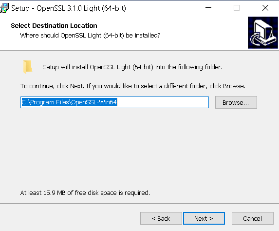
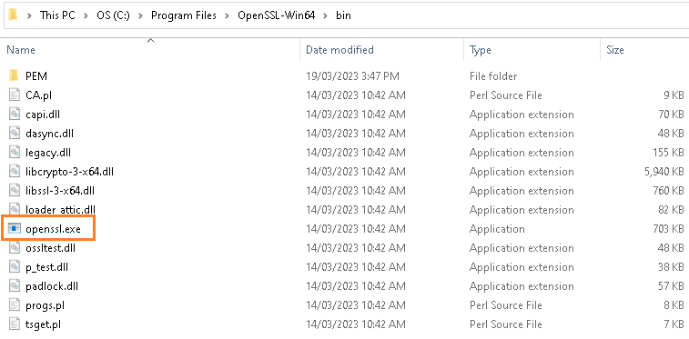
Once the installation process is finish, we can find openssl.exe under program files folder.
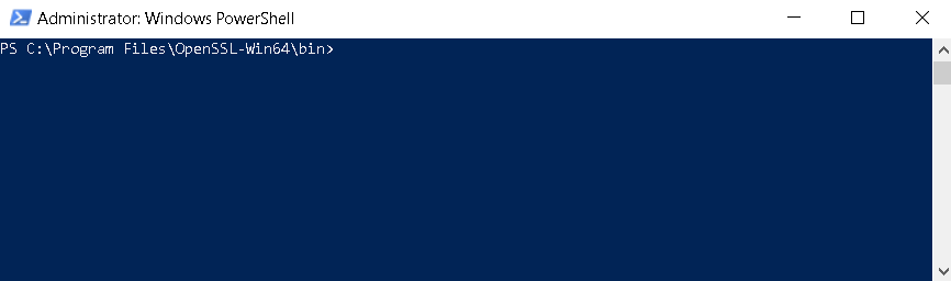
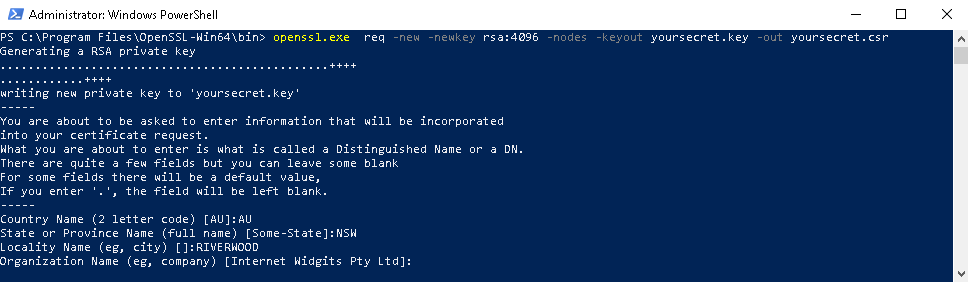
Now, open your Windows PowerShell with administrator privilege and go to the directory where that openssl.exe is residing.
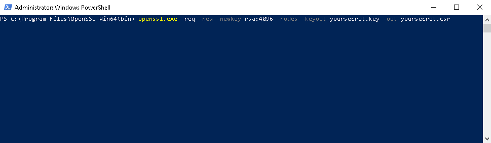
On the prompt type openssl.exe req -new -newkey rsa:4096 -nodes -keyout yoursecret.key -out yoursecret.csr.
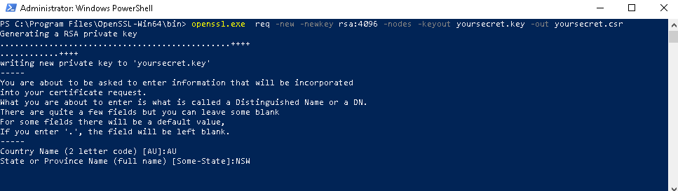
Once you hit ENTER, the prompt will ask you many different things. First it will ask you about what country you are going to use the certificate for. Because i am living in Australia, so i just type AU.

Then it will ask you about the state or province you are living. Because i am living in New South Wales, so i typed in NSW.
Now, it is asking the name of the city you are living.
It will be asking you Organization Name, Organization Unit Name, Domain name if any, then email address and the challenging password.

After completing all those prompted questions, now you can see the generated pem file


blah
SIMPLE CHARTING ON .NET FRAMEWORK 4.7.2
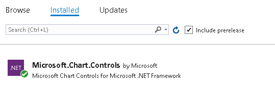
Creating a simple chart and save it as an image file is very handy in .NET FRAMEWORK 4.7.2. On your project you just need to add a package called Microsoft.Chart.Controls.
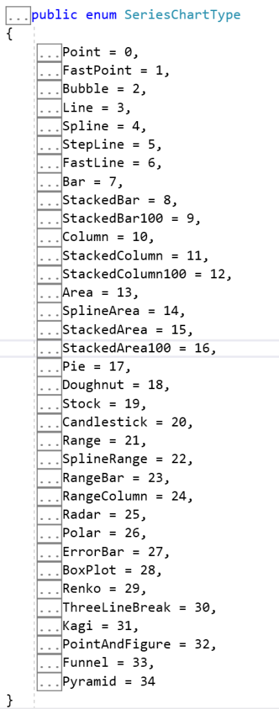
This nuget package supports upto 34 different chart type.
Copy and paste the following code below on your .NET Framework console project.
using System.IO;
using System.Drawing;
using System.Runtime.Serialization.Json;
using System.Windows.Forms.DataVisualization.Charting;

namespace ConsoleApp5
{
    class Program
    {
        static void Main(string[] args)
        {
            // Create a chart object
            Chart chart = new Chart();

            // Set chart title and dimensions
            chart.Titles.Add("Alarm History");
            chart.Size = new Size(1000, 800);

            // Create a chart area and add it to the chart
            ChartArea chartArea = new ChartArea();
            chartArea.Name = "Sample Chart Area";
            chart.ChartAreas.Add(chartArea);

            // Create a data series and add it to the chart
            Series series1 = new Series();
            series1.LegendText = "Front Freezer";
            series1.Color = Color.Red;
            series1.BorderWidth = 5;
            series1.Points.AddXY("08/22", 700);
            series1.Points.AddXY("09/22", 450);
            series1.Points.AddXY("10/22", 550);
            series1.Points.AddXY("11/22", 518);
            series1.Points.AddXY("12/22", 460);
            series1.Points.AddXY("01/23", 670);
            series1.Points.AddXY("02/23", 745);
            series1.ChartType = SeriesChartType.Line;

            Series series2 = new Series();
            series2.LegendText = "Cool Room";
            series2.Color = Color.Blue;
            series2.BorderWidth = 5;
            series2.Points.AddXY("08/22", 530);
            series2.Points.AddXY("09/22", 600);
            series2.Points.AddXY("10/22", 800);
            series2.Points.AddXY("11/22", 828);
            series2.Points.AddXY("12/22", 850);
            series2.Points.AddXY("01/23", 810);
            series2.Points.AddXY("02/23", 805);
            series2.ChartType = SeriesChartType.Line;
            chart.Series.Add(series1);
            chart.Series.Add(series2);

            Legend legend1 = new Legend();
            legend1.Enabled = true;
            legend1.Docking = Docking.Bottom;
            chart.Legends.Add(legend1);

            // Save the chart as an image file
            using (MemoryStream ms = new MemoryStream())
            {
                chart.SaveImage(ms, ChartImageFormat.Png);
                byte[] imageBytes = ms.ToArray();
                File.WriteAllBytes(@"c:\sample_chart.png", imageBytes);
            }
        }
    }
}
The output of the running code look like this.

Click here to download the code.
ADDING DEPENDENCY INJECTION ON CONSOLE APPLICATIONS
To implement DEPENDENCY INJECTION natively on .NET CORE, we need to import one of Microsoft Extensions library, in this case Microsoft.Extensions.DependencyInjection. In this article i am using Visual Studio 2019 and .NET CORE 5.
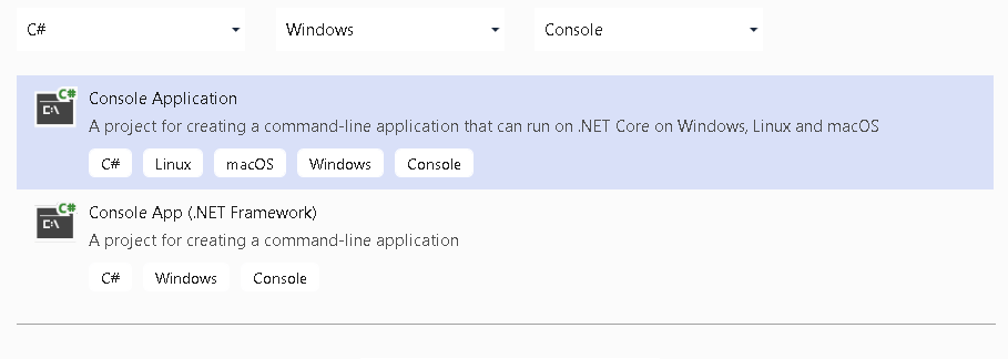
Open your Visual Studio 2019 and select Console Application.
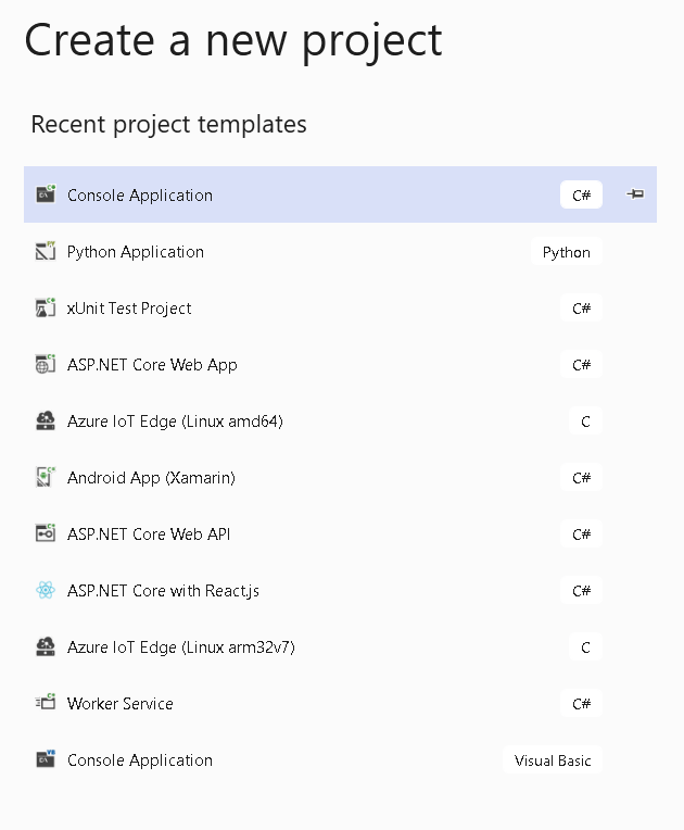
I this case i am going to use C#. Click Next.
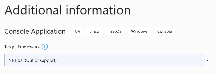
Name the project DI_On_Console

Choose .NET 5.0 as our Target Framework. Then click Create.
Your Visual Studio will greet you with a simple main program for you to start with.
using System;

namespace DI_On_Console
{
    class Program
    {
        static void Main(string[] args)
        {
            Console.WriteLine("Hello World!");
        }
    }
}
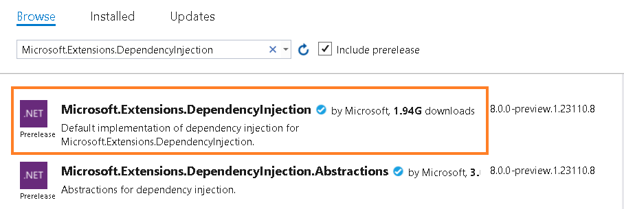
On Solution Explorer, select Dependencies. Right click then select Manage Nuget Packages.

On Browse, search for Microsoft.Extensions.DependencyInjection. Select that one and click Enter.
The next step is to create an interface on new file named as IHelloWorld,cs
namespace DI_On_Console
{
    public interface IHelloWorld
    {

        public string GetString();
    }
}
Create a class to implent that interface. Name this file HelloWorld.cs.
namespace DI_On_Console
{
    class HelloWorld : IHelloWorld
    {
        public string GetString()
        {
            return "Hello World!";
        }
    }
}
We need ServiceCollection to register our newly interface and its implemented class and use GetService method create an instance of that class.
using System;
using Microsoft.Extensions.DependencyInjection;

namespace DI_On_Console
{
    class Program
    {
        static void Main(string[] args)
        {
            IServiceCollection services = new ServiceCollection();
            services.AddScoped<IHelloWorld, HelloWorld>();

            IServiceProvider provider = services.BuildServiceProvider();
            IHelloWorld instance = provider.GetService<IHelloWorld>();
            string value = instance.GetString();
            Console.WriteLine(value);
            Console.ReadLine();
        }
    }
}
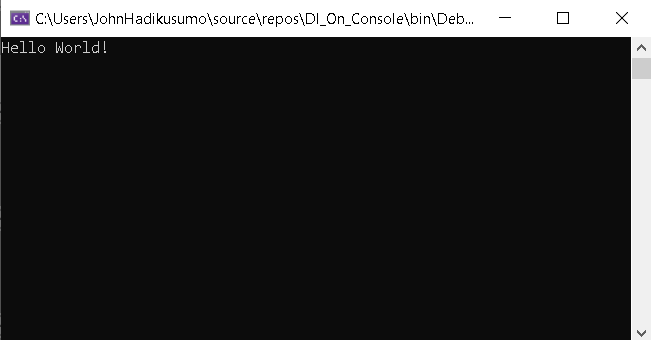
If you run a the code about, it would give the Hello World! as seen below.
INSTALLING RASPBIAN OS ON YOUR RASPBERRY PI 4
First thing first, you need to insert your sd card into your computer sd card reader slot. After that download Raspberry Pi Imager from Raspberry Pi website by clicking here. By default the website can detect what OS that is running on your computer and give you default highlighted download button. Because my computer is running on window, so the windows version is the one that is highlighted.

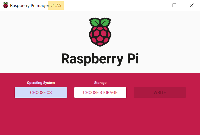
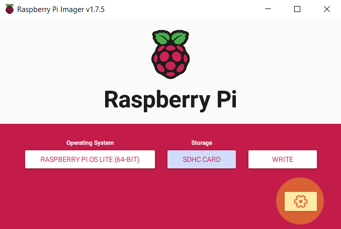
Once the installer downloaded (on my computer it went to download folder), double click to run it. On the pop up window you will see three clickable buttons in series. At the time this article is written, the latest Raspbian OS installer version is 1.7.5.
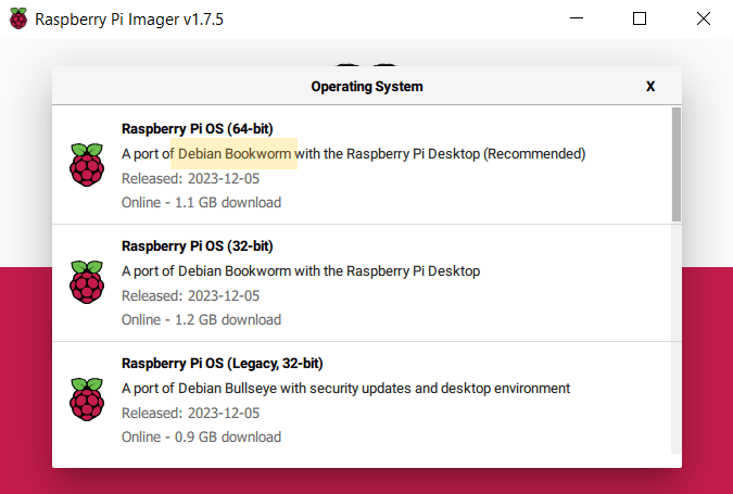
Click CHOOSE OS button. A drop down list will appear to give you a list of Raspberry PI OS you wish to install. It seems Debian Bookworm is the latest version at the time being.
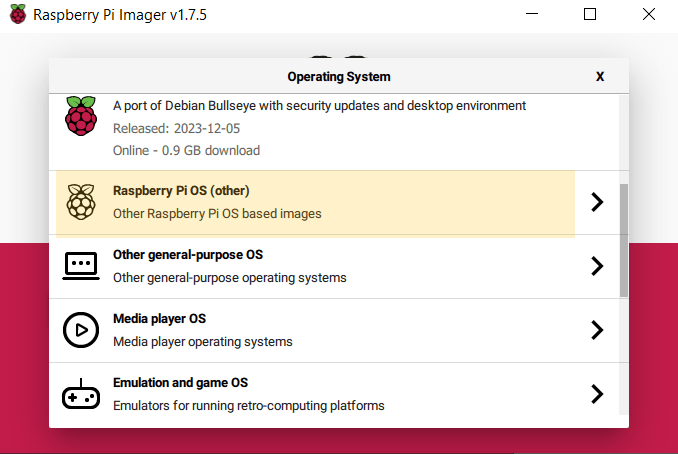
I am going to choose Debian Bookworm with out Desktop because i just want to run the light version without desktop GUI access. So, i scrolled a little bit down and select Raspberry Pi OS (other).
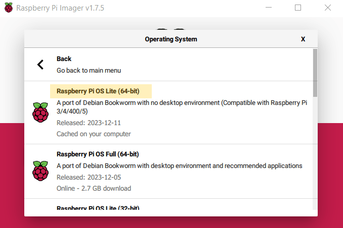
On the next option list, select Raspberry Pi OS Lite (64-bit).
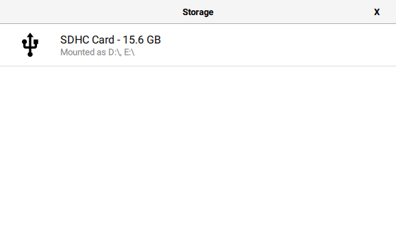
Click CHOOSE STORAGE button. On storage selection list, select Raspberry Pi OS Lite(64-bit)
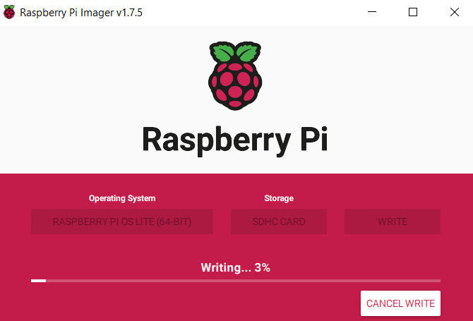
We need to setup internet access so our Raspberry Pi is able to download all necessary packages from the internet. Click the cork at the bottom right of the window.
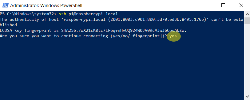
Tick Set hostname. Type raspberrypi on text box. We are going to see this raspberry pi named as raspberrypi.local on our local network.

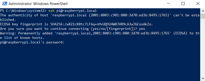
We are going to access this raspberry pi via SSH. Tick on Enable SSH. Select Use password authentication. Then tick on Set username and password. For this exercise i going to use pi as username and pi123** for the password.

This step i want to connect my raspberry pi to my wifi network. So tick on Configure wireless LAN checkbox. Provide your home wifi ssid and the password. For Wireless LAN country drop down options, i choose AU because i am living in Australia.

blah

blah
blah

blah